WO2023132322A1 - 切削インサート、切削工具、及び切削加工物の製造方法 - Google Patents
切削インサート、切削工具、及び切削加工物の製造方法 Download PDFInfo
- Publication number
- WO2023132322A1 WO2023132322A1 PCT/JP2022/048586 JP2022048586W WO2023132322A1 WO 2023132322 A1 WO2023132322 A1 WO 2023132322A1 JP 2022048586 W JP2022048586 W JP 2022048586W WO 2023132322 A1 WO2023132322 A1 WO 2023132322A1
- Authority
- WO
- WIPO (PCT)
- Prior art keywords
- rising
- cutting
- rising surface
- corner
- chips
- Prior art date
Links
Images


Classifications
-
- B—PERFORMING OPERATIONS; TRANSPORTING
- B23—MACHINE TOOLS; METAL-WORKING NOT OTHERWISE PROVIDED FOR
- B23B—TURNING; BORING
- B23B27/00—Tools for turning or boring machines; Tools of a similar kind in general; Accessories therefor
- B23B27/007—Tools for turning or boring machines; Tools of a similar kind in general; Accessories therefor for internal turning
-
- B—PERFORMING OPERATIONS; TRANSPORTING
- B23—MACHINE TOOLS; METAL-WORKING NOT OTHERWISE PROVIDED FOR
- B23B—TURNING; BORING
- B23B27/00—Tools for turning or boring machines; Tools of a similar kind in general; Accessories therefor
- B23B27/14—Cutting tools of which the bits or tips or cutting inserts are of special material
- B23B27/16—Cutting tools of which the bits or tips or cutting inserts are of special material with exchangeable cutting bits or cutting inserts, e.g. able to be clamped
-
- B—PERFORMING OPERATIONS; TRANSPORTING
- B23—MACHINE TOOLS; METAL-WORKING NOT OTHERWISE PROVIDED FOR
- B23B—TURNING; BORING
- B23B31/00—Chucks; Expansion mandrels; Adaptations thereof for remote control
- B23B31/005—Cylindrical shanks of tools
-
- B—PERFORMING OPERATIONS; TRANSPORTING
- B23—MACHINE TOOLS; METAL-WORKING NOT OTHERWISE PROVIDED FOR
- B23B—TURNING; BORING
- B23B2222/00—Materials of tools or workpieces composed of metals, alloys or metal matrices
- B23B2222/28—Details of hard metal, i.e. cemented carbide
-
- B—PERFORMING OPERATIONS; TRANSPORTING
- B23—MACHINE TOOLS; METAL-WORKING NOT OTHERWISE PROVIDED FOR
- B23B—TURNING; BORING
- B23B2222/00—Materials of tools or workpieces composed of metals, alloys or metal matrices
- B23B2222/88—Titanium
-
- B—PERFORMING OPERATIONS; TRANSPORTING
- B23—MACHINE TOOLS; METAL-WORKING NOT OTHERWISE PROVIDED FOR
- B23B—TURNING; BORING
- B23B31/00—Chucks; Expansion mandrels; Adaptations thereof for remote control
- B23B31/02—Chucks
- B23B31/10—Chucks characterised by the retaining or gripping devices or their immediate operating means
- B23B31/107—Retention by laterally-acting detents, e.g. pins, screws, wedges; Retention by loose elements, e.g. balls
- B23B31/1075—Retention by screws
Definitions
- the present disclosure relates to a cutting insert, a cutting tool, and a method of manufacturing a cut product used for cutting a work material.
- the cutting of the work material includes, for example, turning and milling.
- Turning includes, for example, outer diameter machining, inner diameter machining, grooving and parting off.
- Patent Document 1 discusses a cutting tool used for cutting a work material made of a metal material or the like.
- the cutting tool described in Patent Document 1 has a cutting insert and a holder.
- a cutting insert has a rake face, a flank face, a cutting edge and a wall surface.
- the rake face slopes downward with distance from the cutting edge, and the wall surface slopes upward with distance from the rake face.
- a cutting insert according to the present disclosure has a rod-shaped first portion extending along a central axis from a tip toward a rear end, and a second portion protruding from the tip in a direction orthogonal to the central axis.
- the second portion has a triangular shape when viewed from the front, and includes a first corner projecting from the first portion, a first side extending from the first corner toward the first portion, and the first corner protruding from the first portion.
- a second side extending from one corner toward the first portion and located closer to the rear end than the first side; the first corner, the first side, and the second side; a cutting edge located on at least a part of a side; a rising surface located closer to the first portion than the top surface and inclined upward as the distance from the top surface increases; It has an upper end surface located near the part, and a connecting surface having a concave shape located between the top surface and the rising surface and connected to the top surface and the rising surface. Further, in a cross section orthogonal to the upper end surface and including the bisector of the first angle, the imaginary extension line of the upper surface and the imaginary extension line of the rising surface intersect at an acute angle.
- FIG. 1 is a perspective view of a non-limiting one-sided cutting insert of the present disclosure
- FIG. 2 is an enlarged view of a region A1 shown in FIG. 1
- FIG. 3 is an enlarged view of a region A2 shown in FIG. 2
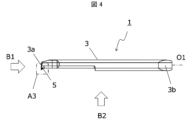
- FIG. 2 is a top view of the cutting insert shown in FIG. 1 as seen from above
- FIG. 5 is an enlarged view of a region A3 shown in FIG. 4
- FIG. 6 is an enlarged view of a region A4 shown in FIG. 5
- FIG. It is the side view which looked at the cutting insert shown in FIG. 4 from B1 direction. It is the side view which looked at the cutting insert shown in FIG. 4 from B2 direction.
- FIG. 9 is an enlarged view of a region A5 shown in FIG. 8;
- FIG. 9 is an enlarged view of a region A5 shown in FIG. 8;
- FIG. 9 is an enlarged view of a region A5 shown in FIG. 8;
- FIG. 9 is an enlarged view of
- FIG. 10 is an enlarged view of a region A6 shown in FIG. 9;
- FIG. 7 is a cross-sectional view showing the XI-XI cross section in FIG. 6;
- FIG. 7 is a sectional view showing the XII-XII section in FIG. 6;
- 1 is a perspective view of a non-limiting one-sided cutting tool of the present disclosure;
- FIG. 14 is a top view of the cutting tool shown in FIG. 13;
- FIG. 1 is a schematic diagram illustrating a step in the non-limiting method of manufacturing a one-sided machined workpiece of the present disclosure;
- FIG. 1 is a schematic diagram illustrating a step in the non-limiting method of manufacturing a one-sided machined workpiece of the present disclosure;
- FIG. 1 is a schematic diagram illustrating a step in the non-limiting method of manufacturing a one-sided machined workpiece of the present disclosure;
- FIG. 1 is a schematic diagram illustrating a step in the non-limiting method of manufacturing
- a non-limiting one-sided cutting insert 1 (hereinafter also simply referred to as insert 1) in the present disclosure will be described in detail with reference to the drawings.
- insert 1 may comprise any components not shown in the referenced figures.
- the dimensions of the members in each drawing do not necessarily represent the actual dimensions of the constituent members, the dimensional ratios of the respective members, and the like faithfully.
- the insert 1 is generally rod-shaped overall and has a first portion 3 and a second portion 5, as in the non-limiting example shown in FIG.
- the first portion 3 is a bar-shaped portion extending along the central axis O1 from the front end 3a toward the rear end 3b, and serves as the base of the insert 1.
- the first portion 3 in one non-limiting example shown in FIG. 1 is generally cylindrical.
- the insert 1 is fixed to the holder by attaching the first portion 3 to a holder which will be described later.
- the “central axis O1” is an axis along the longitudinal direction of the first portion 3, and the center of at least either the front end 3a side or the rear end 3b side of the first portion 3 is It is the axis that passes through.
- an axis along the longitudinal direction passing through the center of gravity of the first portion 3 when viewed from the rear end 3b side may be regarded as the central axis O1.
- the size of the first part 3 is not limited to a specific value.
- the length of the first portion 3 in the direction along the central axis O1 can be set to 30 to 80 mm, for example.
- the maximum width of the first portion 3 in the direction orthogonal to the central axis O1 can be set to 3 to 10 mm, for example.
- the second portion 5 protrudes in a direction orthogonal to the central axis O1 from a portion of the first portion 3 on the tip 3a side. At this time, the second portion 5 may not protrude from the portion including the tip 3a of the first portion 3, but in a non-limiting example shown in FIG. It protrudes in a direction perpendicular to the central axis O1 from the portion including the .
- the second portion 5 has a cutting edge 7 as described later, and plays a major role during cutting of the work material. Therefore, the first portion 3 of the insert 1 may be called the base portion, and the second portion 5 may be called the cutting portion.
- the first part 3 and the second part 5 may be separate members, or may be integrally formed. In one non-limiting example shown in FIG. 1, the first part 3 and the second part 5 are integrally formed.
- the second part 5 has an upper surface 9 , a cutting edge 7 , a rising surface 11 , an upper end surface 5 a and a connecting surface 13 .
- the top surface 9 is triangular with a first corner 15 , a first side 17 and a second side 19 .
- a first corner 15 of the upper surface 9 protrudes in a direction orthogonal to the central axis O1. Therefore, the first corner 15 is the farthest from the first portion 3 on the upper surface 9 .
- the first corner 15 need not be a corner in the strict sense.
- the first corner 15 in one non-limiting example shown in FIG.
- the first corner 15 may be arc-shaped.
- the first side 17 and the second side 19 extend from the first corner 15 respectively.
- the first side 17 and the second side 19 each extend from the first corner 15 toward the first portion 3 .
- the distance between the first side 17 and the second side 19 increases with increasing distance from the first corner 15 .
- the first side 17 is located on the side of the leading edge 3a and the second side 19 is located on the side of the trailing edge 3b. That is, the second side 19 is located closer to the rear end 3b than the first side 17 is.
- the first side 17 and the second side 19 may each have a linear shape.
- the size of the upper surface 9 is not limited to a specific value.
- the width of the upper surface 9 in the direction along the central axis O1 when viewed from the front can be set to 0.1 to 3 mm, for example.
- the width of the upper surface 9 in the direction orthogonal to the central axis O1 when viewed from the front can be set to 0.08 to 2 mm, for example.
- viewing the upper surface 9 from the front may be referred to as viewing from the top.
- a first side 17, a second side 19, and a first corner 15 on the upper surface 9 are separated from the first portion 3, and form an outer edge of the insert 1 when viewed from above.
- the cutting edge 7 is located on at least part of the first side 17 , the second side 19 and the first corner 15 . By bringing this cutting edge 7 into contact with the work material, the work material can be cut.
- the rising surface 11 is a surface located closer to the first part 3 than the top surface 9 and is inclined with respect to the top surface 9 . Specifically, the rising surface 11 is inclined upward with distance from the upper surface 9 .
- the rising surface 11 is a surface positioned forward in the traveling direction of chips generated by the cutting edge 7 , and the chips can come into contact with the rising surface 11 . By bringing the chips into contact with the rising surface 11, the chips can be controlled by slowing down the flow speed of the chips, changing the direction of the flow of the chips, and deforming the chips.
- the upper end surface 5 a is a surface positioned closer to the first portion 3 than the rising surface 11 and is the surface positioned highest in the second portion 5 .
- the top surface 5a in one non-limiting example shown in FIG. 5 is flat.
- the upper end surface 5a in the non-limiting example shown in FIG. 10 is parallel to the central axis O1.
- the upper end surface 5a may be used as a reference plane for adjusting the position of the cutting edge 7 in the vertical direction.
- the upper surface 9 in the non-limiting example shown in FIG. 10 is slightly inclined with respect to the upper end surface 5a. Specifically, when the upper end face 5a is used as a reference plane, the upper face 9 is slightly inclined downward as it approaches the rear end 3b.
- connection surface 13 is located between the top surface 9 and the rising surface 11 and is connected to the top surface 9 and the rising surface 11 .
- top surface 9 and rising surface 11 are flat, while connecting surface 13 is concave.
- the connecting surface 13 is indicated by a concave curve.
- a surface formed by the upper surface 9, the rising surface 11, and the connecting surface 13 of the second portion 5 has a concave shape as a whole.
- the bisector of the first angle 15 may be replaced with the bisector of the angle formed by the tangents at both ends of the first angle, for example, when the first angle 15 has a convex curved shape or an arc shape. . Further, for example, when the first corner 15 is connected to the first side 17 and the second side 19 and the first side 17 and the second side 19 are linear, the first side 17 and the second side 19 are connected to each other.
- the angle formed by the imaginary extension lines extending from the sides 19 may be replaced with the bisector of the first angle 15 .
- the cross section including the bisector of the first angle 15 is a cross section including the entire bisector of the first angle 15 . In the cutting tool of the present disclosure, for convenience of explanation, a part of the above-described first cross section is enlarged and shown in the drawing.
- the upper surface 9 is slightly inclined with respect to the upper end surface 5a. Therefore, the first cross section is perpendicular to the upper end surface 5 a and is inclined with respect to the upper surface 9 . "Oblique” here is intended to be neither orthogonal nor parallel. The first cross section may be inclined with respect to the upper surface 9 and perpendicular to the rising surface 11 .
- the insert 1 does not have the connection surface 13 and the top surface 9 and the rising surface 11 are connected, chips may clog near the boundary between the top surface 9 and the rising surface 11 .
- the connecting surface 13 having a concave surface shape is positioned between the upper surface 9 and the rising surface 11, chip clogging is less likely to occur.
- the second part 5 may have side surfaces 21 .
- the side surfaces 21 are connected to the first corner 15 , the first side 17 and the second side 19 of the top surface 9 . Therefore, it can be said that the cutting edge 7 is located at the intersection of the upper surface 9 and the side surface 21 .
- a side surface 21 located along the cutting edge 7 may function as a so-called clearance surface.
- the upper surface 9 may function as a so-called rake surface.
- the side surface 21 may have a first side surface 21a, a second side surface 21b and a corner side surface 21c.
- the first side surface 21 a is connected to the first side 17 .
- the second side surface 21 b is connected to the second side 19 .
- the corner side 21 c is connected to the first corner 15 .
- the first side 21a connected to the first side 17 and the second side 21b connected to the second side 19 may each be flat.
- the side surface 21 functions as a flank
- the first side surface 21a and the second side surface 21b may approach each other as the distance from the upper surface 9 increases.
- the corner side surface 21c connected to the first corner 15 may have a convex curved shape.
- the imaginary extension line L1 of the upper surface 9 and the imaginary extension line L2 of the rising surface 11 may intersect at an acute angle. If these imaginary extension lines L1 and L2 intersect at an obtuse angle, depending on the cutting conditions, it may be difficult to sufficiently reduce the flow rate of chips on the rising surface 11 . Therefore, there is a possibility that the control of the chips becomes difficult when the chips climb over the rising surface 11 .
- the flow speed of chips can be sufficiently slowed down, and the chips tend to curl.
- the chips tend to advance parallel to the upper surface 9 .
- the chips tend to advance parallel to the rising surface 11 .
- the traveling direction of the chips traveling along the rising surface 11 includes a component that is reversed with respect to the traveling direction of the chips traveling along the upper surface 9 . Therefore, chips tend to curl as described above.
- the angle ⁇ at which imaginary extension lines L1 and L2 intersect in the first cross section is not limited to a specific value as long as it is an acute angle.
- the angle ⁇ may be set to, for example, approximately 75° to 89.8°. When the angle ⁇ is 75° or more, the connecting surface 13 is less likely to be clogged with chips. Further, when the angle ⁇ is 89.8° or less, chips are stable and tend to curl.
- the virtual extension lines L1 and L2 may be evaluated by the following procedure. First, in the first cross section, a tangent line that contacts the top surface 9 and the connection surface 13 at the boundary between the top surface 9 and the connection surface 13 is specified. This tangent line may be the imaginary extension line L1. Also, in the first cross section, a tangent line that contacts the rising surface 11 and the connecting surface 13 at the boundary between the rising surface 11 and the connecting surface 13 is specified. This tangent line may be the imaginary extension line L2.
- connection surface 13 in a non-limiting example shown in FIG. 6 has a groove shape extending in a direction inclined with respect to the central axis O1. At this time, the groove-shaped connecting surface 13 may be inclined away from the central axis O1 as it approaches the rear end 3b.
- the inclination angle ⁇ 1 of the extending direction of the connecting surface 13 with respect to the central axis O1 when viewed from above is not limited to a specific value, and may be 0° ⁇ 90°. In particular, when the inclination angle ⁇ 1 satisfies 0° ⁇ 45°, the chip discharging property is excellent. When chips come into contact with the connection surface 13 and change direction of flow, if the inclination angle ⁇ 1 is greater than 45°, the chips tend to flow in the direction perpendicular to the central axis O1, but the inclination angle ⁇ 1 is greater than 45°. This is because chips tend to flow toward the rear end 3b when they are small.
- the portion of the cutting edge 7 located on the first side 17 is called the major cutting edge 7 and is often used as the main edge in cutting. This is because the chips generated by the main cutting edge 7 located on the first side 17 tend to advance toward the rear end 3b, resulting in excellent chip discharging performance.
- the groove-shaped connection surface 13 is inclined as described above, chips traveling toward the rear end 3b are likely to come into contact with the connection surface 13 . Therefore, it is easy to control the flow of chips on the connection surface 13 .
- the rising surface 11 may be inclined with respect to the central axis O1 so as to move away from the central axis O1 as it approaches the rear end 3b when viewed from above. In this case, chips advancing toward the rear end 3 b easily come into contact with the rising surface 11 . Therefore, the flow of chips is easily controlled on the rising surface 11 .
- the upper surface 9 may be parallel to the central axis O1, or may be inclined.
- the upper surface 9 may slope downward as it approaches the rear end 3b.
- an imaginary straight line O2 parallel to the central axis O1 is set to facilitate visual understanding of the tilt angle ⁇ 2, and the angle formed by the imaginary straight line O2 and the top surface 9 indicates the tilt angle ⁇ 2.
- connection surface 13 may be open to the second side surface 21b. Chips whose flow is controlled at the connection surface 13 tend to stably advance toward the rear end 3b, and the insert 1 tends to be excellent in chip discharging performance. Also, the connection surface 13 may be open to the first side surface 21a.
- connection surface 13 is open to the first side surface 21a, even when chips advance toward the tip 3a, the chip discharging performance is excellent. That is, when the connection surface 13 is open to the first side surface 21a and the second side surface 21b, the insert 1 is less subject to structural limitations of the work material and has excellent versatility.
- the width W1 of the rising surface 11 may increase as it moves away from the first side 17 and approaches the second side 19 .
- the flow direction of the chips tends to vary more as it approaches the rear end 3b, in other words, as it moves away from the first side 17 and approaches the second side 19.
- the width W1 of the rising surface 11 is configured as described above, the flow of chips can be stably controlled even if the direction of the flow of chips varies.
- the width W1 of the entire rising surface 11 is not large, the size of the insert 1 can be reduced.
- the width W2 of the connection surface 13 may be constant from the first side 17 toward the second side 19. Chips tend to curl when they come into contact with the connecting surface 13 having a concave surface shape. If the width W2 of the connecting surface 13 changes from the first side 17 toward the second side 19, the chips tend to curl into a truncated cone shape as a whole. Therefore, chips tend to form large clumps. On the other hand, when the width W2 of the connecting surface 13 is constant as described above, the chips as a whole tend to have an elongated shape such as a spiral shape. Therefore, it is excellent in chip discharge property.
- the width W2 of the connecting surface 13 may be larger than the width W1 of the rising surface 11 in the first cross section as in a non-limiting example shown in FIG. In such a case, since the space of the connection surface 13 is easily secured, the chips tend to curl stably and clogging of the chips is less likely to occur, resulting in excellent chip discharging performance.
- the upper surface 9 and the rising surface 11 may each be flat. If the upper surface 9 is flat, the contact area of the chips on the upper surface 9 and the rising surface 11 can be reduced when the chips pass over the upper surface 9, the connecting surface 13 and the rising surface 11 while curling. Therefore, the upper surface 9 and the rising surface 11 are less likely to wear, and the durability of the insert 1 is high.
- connection surface 13 may be arc-shaped, and the radius of curvature R1 of the connection surface 13 may be larger than the width W1 of the rising surface 11. In such a case, since the chips tend to curl gently, chip clogging is less likely to occur and chip discharge is excellent.
- connection surface 13 in the first cross section has an arc shape
- the curvature radius R1 of the connection surface 13 may be constant from the first side 17 toward the second side 19 .
- the chips as a whole tend to have an elongated shape such as a helical shape rather than a truncated cone shape. Therefore, it is excellent in chip discharge property.
- the connecting surface 13 may have an elliptical arc shape, and the maximum value of the curvature radius R1 of the connecting surface 13 may be larger than the width W1 of the rising surface 11.
- it is vertically elongated, in other words, it has an elliptical arc shape whose major axis is in the vertical direction. In such a case, the chips smoothly progress from the connecting surface 13 to the rising surface 11, so that chip clogging is less likely to occur and the chip discharging performance is excellent.
- Constant does not have to be exactly the same value. This is a concept that allows for variations that are unavoidable in manufacturing. Specifically, if the minimum value is 95% or more of the maximum value, it may be evaluated as constant. For example, when the width W2 of the connection surface 13 is constant from the first side 17 to the second side 19, the minimum value of the width W2 of the connection surface 13 is 95 times the maximum value of the width W2 of the connection surface 13. ⁇ 100% is sufficient.
- Examples of materials for the insert 1 include cemented carbide and cermet.
- Cemented carbide compositions may include, for example, WC-Co, WC-TiC-Co and WC-TiC-TaC-Co.
- WC, TiC and TaC may be hard particles and Co may be the binder phase.
- the cermet may be a sintered composite material in which a metal is combined with a ceramic component.
- An example of a cermet may be a titanium compound based on titanium carbide (TiC) or titanium nitride (TiN).
- TiC titanium carbide
- TiN titanium nitride
- the material of the insert 1 is not limited to the above composition.
- the surface of the insert 1 may be coated with a coating using chemical vapor deposition (CVD) or physical vapor deposition (PVD) methods.
- the composition of the coating may include titanium carbide (TiC), titanium nitride (TiN), titanium carbonitride (TiCN), alumina (Al 2 O 3 ), and the like.
- the cutting tool 101 may have a bar-shaped holder 105 extending from the first end 105a toward the second end 105b, as in a non-limiting example shown in FIGS.
- the holder 105 may have a pocket 103 (insert pocket) located on the side of the first end 105a.
- the cutting tool 101 may comprise the insert 1 described above located in the pocket 103 .
- the insert 1 may be mounted such that at least part of the cutting edge 7 protrudes from the first end 105 a of the holder 105 .
- the holder 105 may have an elongated bar shape.
- One pocket 103 may be provided on the first end 105a side of the holder 105 .
- the pocket 103 is a portion to which the insert 1 is mounted, and may be open to the end face of the holder 105 on the side of the first end 105a.
- the insert 1 may be fixed to the holder 105 by screws 107, as a non-limiting example shown in FIG.
- the holder 105 may be provided with a threaded hole, and the insert 1 may be constrained in the pocket 103 by inserting the screw 107 into the threaded hole and pressing the screw 107 against the insert 1 .
- Steel, cast iron, or the like may be used as the member of the holder 105 .
- the toughness of the holder 105 is high.
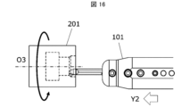
- the cutting work 203 is produced by cutting the work material 201 .
- the manufacturing method of the cut workpiece 203 in the embodiment includes the following steps. i.e. (1) a step of rotating the work material 201; (2) contacting the rotating work material 201 with the cutting tool 101 represented by the above embodiment; (3) separating the cutting tool 101 from the work material 201; Prepare.
- the work material 201 may be rotated around the axis O3 and the cutting tool 101 may be brought relatively closer to the work material 201.
- the cutting tool 101 may be brought relatively closer to the work material 201.
- at least a portion of the cutting edge 7 of the cutting tool 101 may be brought into contact with the work material 201 to cut the work material 201 .
- the cutting tool 101 may be kept relatively away from the work material 201 .
- the cutting tool 101 is moved in the Y1 direction with the axis O3 fixed and the work material 201 rotated, thereby bringing the cutting tool 101 closer to the work material 201. good too.
- the cutting tool 101 is moved in the Y2 direction while at least a portion of the cutting edge 7 of the insert 1 is in contact with the rotating work 201. You may cut the cut material 201 by making it carry out.
- the cutting tool 101 may be moved away from the work material 201 by moving the cutting tool 101 in the Y3 direction while the work material 201 is being rotated.
- the cutting tool 101 In each process, by moving the cutting tool 101, the cutting tool 101 is brought into contact with the work material 201, or the cutting tool 101 is separated from the work material 201, but it is of course not limited to such a form. .
- step (1) the work material 201 may be brought closer to the cutting tool 101 . Also, in the step (3), the work material 201 may be kept away from the cutting tool 101 . When cutting is continued, the process of keeping the work material 201 rotated and bringing at least part of the cutting edge 7 of the insert 1 into contact with a different location on the work material 201 may be repeated. .
- Representative examples of the material of the work material 201 include hardened steel, carbon steel, alloy steel, stainless steel, cast iron, non-ferrous metals, and the like.
- Cutting insert (insert) 3 First portion 3a Front end 3b Rear end 5 Second portion 5a Upper end surface 7 Cutting edge 9 Upper surface 11 Rising surface 13 Connection Surface 15 First corner 17 First side 19 Second side 21 Side 21a First side 21b Second side 21c Corner side 101 Cutting tool 103... Pocket 105... Holder 107... Screw 201... Work material 203... Cut workpiece O1... Center axis O2... Imaginary straight line L1...
Landscapes
- Engineering & Computer Science (AREA)
- Mechanical Engineering (AREA)
- Cutting Tools, Boring Holders, And Turrets (AREA)
Priority Applications (4)
| Application Number | Priority Date | Filing Date | Title |
|---|---|---|---|
| DE112022006296.7T DE112022006296T5 (de) | 2022-01-05 | 2022-12-28 | Schneideinsatz, schneidwerkzeug und verfahren zur herstellung eines maschinell bearbeiteten produkts |
| CN202280084349.0A CN118434520A (zh) | 2022-01-05 | 2022-12-28 | 切削刀片、切削刀具以及切削加工物的制造方法 |
| US18/724,193 US20250222528A1 (en) | 2022-01-05 | 2022-12-28 | Cutting insert, cutting tool, and method for manufacturing machined product |
| JP2023572469A JP7692062B2 (ja) | 2022-01-05 | 2022-12-28 | 切削インサート、切削工具、及び切削加工物の製造方法 |
Applications Claiming Priority (2)
| Application Number | Priority Date | Filing Date | Title |
|---|---|---|---|
| JP2022000615 | 2022-01-05 | ||
| JP2022-000615 | 2022-01-05 |
Publications (1)
| Publication Number | Publication Date |
|---|---|
| WO2023132322A1 true WO2023132322A1 (ja) | 2023-07-13 |
Family
ID=87073743
Family Applications (1)
| Application Number | Title | Priority Date | Filing Date |
|---|---|---|---|
| PCT/JP2022/048586 WO2023132322A1 (ja) | 2022-01-05 | 2022-12-28 | 切削インサート、切削工具、及び切削加工物の製造方法 |
Country Status (5)
| Country | Link |
|---|---|
| US (1) | US20250222528A1 (en]) |
| JP (1) | JP7692062B2 (en]) |
| CN (1) | CN118434520A (en]) |
| DE (1) | DE112022006296T5 (en]) |
| WO (1) | WO2023132322A1 (en]) |
Citations (8)
| Publication number | Priority date | Publication date | Assignee | Title |
|---|---|---|---|---|
| EP0157114A2 (de) * | 1984-02-06 | 1985-10-09 | MAPAL Fabrik für Präzisionswerkzeuge Dr. Kress KG | Messerplatte |
| JPH0497609U (en]) * | 1991-01-11 | 1992-08-24 | ||
| JP2009095922A (ja) * | 2007-10-16 | 2009-05-07 | Ngk Spark Plug Co Ltd | 内径加工用工具 |
| WO2017204045A1 (ja) * | 2016-05-26 | 2017-11-30 | 住友電工ハードメタル株式会社 | 振動切削用インサート |
| JP2019042817A (ja) * | 2017-08-29 | 2019-03-22 | 京セラ株式会社 | 切削インサート、切削工具及び切削加工物の製造方法 |
| JP2019509183A (ja) * | 2016-03-22 | 2019-04-04 | ハルトメタル−ウェルクゾーグファブリック ポール ホーン ゲゼルシャフト ミット ベシュレンクテル ハフツング | 切削ツール |
| JP2020163524A (ja) * | 2019-03-29 | 2020-10-08 | 三菱マテリアル株式会社 | 刃先交換式切削工具、切削インサート、および工具本体 |
| CN113385702A (zh) * | 2021-07-09 | 2021-09-14 | 抚州长丰机械有限责任公司 | 一种法兰空心管精加工组合刀具 |
Family Cites Families (1)
| Publication number | Priority date | Publication date | Assignee | Title |
|---|---|---|---|---|
| JP4815366B2 (ja) | 2007-02-27 | 2011-11-16 | 日本特殊陶業株式会社 | 切削用のインサート及びホルダー並びに切削工具 |
-
2022
- 2022-12-28 WO PCT/JP2022/048586 patent/WO2023132322A1/ja active Application Filing
- 2022-12-28 DE DE112022006296.7T patent/DE112022006296T5/de active Pending
- 2022-12-28 US US18/724,193 patent/US20250222528A1/en active Pending
- 2022-12-28 CN CN202280084349.0A patent/CN118434520A/zh active Pending
- 2022-12-28 JP JP2023572469A patent/JP7692062B2/ja active Active
Patent Citations (8)
| Publication number | Priority date | Publication date | Assignee | Title |
|---|---|---|---|---|
| EP0157114A2 (de) * | 1984-02-06 | 1985-10-09 | MAPAL Fabrik für Präzisionswerkzeuge Dr. Kress KG | Messerplatte |
| JPH0497609U (en]) * | 1991-01-11 | 1992-08-24 | ||
| JP2009095922A (ja) * | 2007-10-16 | 2009-05-07 | Ngk Spark Plug Co Ltd | 内径加工用工具 |
| JP2019509183A (ja) * | 2016-03-22 | 2019-04-04 | ハルトメタル−ウェルクゾーグファブリック ポール ホーン ゲゼルシャフト ミット ベシュレンクテル ハフツング | 切削ツール |
| WO2017204045A1 (ja) * | 2016-05-26 | 2017-11-30 | 住友電工ハードメタル株式会社 | 振動切削用インサート |
| JP2019042817A (ja) * | 2017-08-29 | 2019-03-22 | 京セラ株式会社 | 切削インサート、切削工具及び切削加工物の製造方法 |
| JP2020163524A (ja) * | 2019-03-29 | 2020-10-08 | 三菱マテリアル株式会社 | 刃先交換式切削工具、切削インサート、および工具本体 |
| CN113385702A (zh) * | 2021-07-09 | 2021-09-14 | 抚州长丰机械有限责任公司 | 一种法兰空心管精加工组合刀具 |
Also Published As
| Publication number | Publication date |
|---|---|
| CN118434520A (zh) | 2024-08-02 |
| JP7692062B2 (ja) | 2025-06-12 |
| US20250222528A1 (en) | 2025-07-10 |
| JPWO2023132322A1 (en]) | 2023-07-13 |
| DE112022006296T5 (de) | 2024-11-07 |
Similar Documents
| Publication | Publication Date | Title |
|---|---|---|
| EP2682208B1 (en) | Cutting insert, cutting tool, and method for manufacturing cut product using cutting insert and cutting tool | |
| EP3006142B1 (en) | Cutting insert and cutting tool, and method for producing cut workpieces using cutting tool | |
| JP6356781B2 (ja) | 切削インサート、切削工具及び切削加工物の製造方法 | |
| JP6645964B2 (ja) | 切削インサート、切削工具及び切削加工物の製造方法 | |
| JP6861269B2 (ja) | 切削インサート、切削工具及び切削加工物の製造方法 | |
| JP6730442B2 (ja) | 切削インサート、切削工具及び切削加工物の製造方法 | |
| JP6272345B2 (ja) | 切削インサート及び切削工具、並びにそれらを用いた切削加工物の製造方法 | |
| CN111148590B (zh) | 切削刀片、切削刀具以及切削加工物的制造方法 | |
| JP6711842B2 (ja) | 切削インサート、切削工具及び切削加工物の製造方法 | |
| JP7017553B2 (ja) | 切削インサート、切削工具及び切削加工物の製造方法 | |
| WO2017073663A1 (ja) | 切削工具用ホルダ、切削工具及び切削加工物の製造方法 | |
| CN110944783B (zh) | 切削刀片、切削工具以及切削加工物的制造方法 | |
| JP6346200B2 (ja) | 切削インサート、切削工具及び切削加工物の製造方法 | |
| JP7526894B2 (ja) | 回転工具及び切削加工物の製造方法 | |
| WO2023132322A1 (ja) | 切削インサート、切削工具、及び切削加工物の製造方法 | |
| JP6352639B2 (ja) | 切削インサート、切削工具および切削加工物の製造方法 | |
| WO2022118946A1 (ja) | 切削インサート、切削工具及び切削加工物の製造方法 | |
| WO2021005951A1 (ja) | 切削インサート、切削工具及び切削加工物の製造方法 | |
| WO2019004030A1 (ja) | 切削インサート、切削工具及び切削加工物の製造方法 | |
| WO2025063055A1 (ja) | 切削インサート、切削工具、及び切削加工物の製造方法 | |
| WO2023063183A1 (ja) | 切削インサート、切削工具及び切削加工物の製造方法 | |
| JP7023297B2 (ja) | 切削インサート、切削工具及び切削加工物の製造方法 | |
| WO2025094666A1 (ja) | 切削インサート、切削工具、及び切削加工物の製造方法 |
Legal Events
| Date | Code | Title | Description |
|---|---|---|---|
| 121 | Ep: the epo has been informed by wipo that ep was designated in this application |
Ref document number: 22918905 Country of ref document: EP Kind code of ref document: A1 |
|
| WWE | Wipo information: entry into national phase |
Ref document number: 202280084349.0 Country of ref document: CN |
|
| WWE | Wipo information: entry into national phase |
Ref document number: 2023572469 Country of ref document: JP |
|
| WWE | Wipo information: entry into national phase |
Ref document number: 18724193 Country of ref document: US |
|
| WWE | Wipo information: entry into national phase |
Ref document number: 112022006296 Country of ref document: DE |
|
| 122 | Ep: pct application non-entry in european phase |
Ref document number: 22918905 Country of ref document: EP Kind code of ref document: A1 |
|
| WWP | Wipo information: published in national office |
Ref document number: 18724193 Country of ref document: US |